Showing posts with label Arduino. Show all posts

Wednesday, January 03, 2018

Homegrown XY plotter with Arduino

[ This is work in progress and only for myself. If you are looking for ready-made kit, then have e.g. a look at the MaXYposi from German Make Magazine ]

Back in school we had a HP plotter well hidden in some closet in the science department. I was able to play with it for a while and always had the desire to have one on my own (but why, where dot-matrix printers are so much versatile and useful).

Bildschirmfoto 2018 01 03 um 12 11 22
Photo from Plotter in action. Video here.

Fast forward many many years. Stepper motors are easily available, I am back into doing stuff with electronics and micro controllers and recently saw someone creating some displays with engraved acrylic. This triggered me to finally get started with the plotter (and later engraver etc).

To get going I got some parts and as I am an old-school 5V guy, I totally like the original Arduino UNO. In the list, I put in links for reference. I am not affiliated with those companies

  • FabScan shield - physically hosts the Stepper motor drivers
  • SilentStepSticks - motor drivers, as the Arduino itself can't handle the voltage and current that a stepper motor needs. I am using the ones with a Trinamic TMC2130 chip, but in standalone mode for now. Those are replacements for the Pololu 4988, but allow for much quieter operation.
  • StepStick protectors - diodes that prevent the turning motor to fry your motor drivers (you want them, believe me)
  • Stepper motors - I took NEMA 17 ones with 12V (Watterott, Sparkfun)
  • Linear guard rails
  • Wooden base plate
  • Wood, screws, ..
  • GT2 belt, GT2 timing pulley

As you can see in the next picture I started out much too big - I can't really have the plotter sit on my desk comfortably, but anyway :) I did it for learning purposes (and as I have to re-do some things, I'll also use smaller beams).

Hardware side
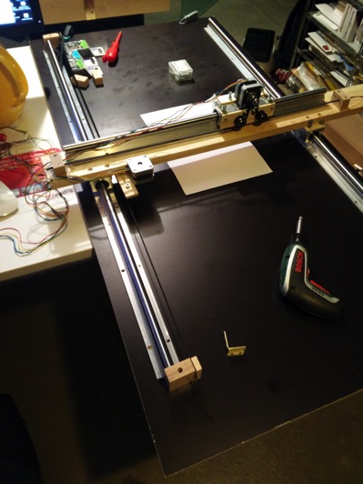
IMG 20180101 185406
View of the plotter base plate with X-axis and Y-axis rails

The belt is mounted on both sides of the rail and then slung around the motor with some helper wheels:


Detail of the belt routing on the motor

On the Arduino side there is a stack of things. On the bottom, the Arduino, then the FabScan shield, then on motor slots 1+2 a StepStick protector and then on top of them the SilentStepSticks. Note that the SCK and SDI pins are not connected

IMG 20180103 110111
Setup on Arduino (see here for a larger image)

Btw be careful with the wires to the motor to correctly attach them. When in doubt have a look at the data sheet or a ohm-meter to figure out which wires belong together.

Software side

I know that there is software like Grbl, that can interpret so called G-codes for tool movement and other things and I could have just flashed that to the Arduino, but I am too curious for that and wanted to better understand things myself.

Basics

To drive a stepper motor with the StepStick driver (or compatibles) one basically needs to send a high and then a low signal to the respective pin. Or in Arduino-terms

digitalWrite(stepPin, HIGH);
delayMicroseconds(30);
digitalWrite(stepPin, LOW);

Where stepPin is the pin number for the stepper - 3 for motor 1 and 6 for motor 2.

Before the stepper does any work, it needs to be enabled.

digitalWrite(enPin, LOW);

Actually the StepStick knows three states for the pin here

  • LOW: motor is enabled
  • HIGH: motor is disabled
  • pin not connected: motor is enabled but goes into some energy saving after a while

When a motor is enabled, its coils are powered and it keeps its position. It is almost impossible to manually turn its axis. This is good for precision purposes, but also means that both motors and driver chips are "flooded" with power and will thus warm up.

And not last but not least, we need a way to determine the direction

digitalWrite(dirPin, direction);

The following table lists the functions and the pins

FunctionMotor1Motor2
enable25
direction47
step36

Before we can use the pins, we need to set them to OUTPUT mode, best in the setup() section of the code

pinMode(enPin1, OUTPUT);
pinMode(stepPin1, OUTPUT);
pinMode(dirPin1, OUTPUT);
digitalWrite(enPin1, LOW);

With that knowledge we can easily get the stepper to move around:

    totalRounds = ...
    for (int rounds =0 ; rounds < 2*totalRounds; rounds++) {
       if (dir==0){ // set direction
         digitalWrite(dirPin2, LOW);
       } else {
         digitalWrite(dirPin2, HIGH);
       }
       delay(1); // give motors some breathing time
       dir = 1-dir; // reverse direction
       for (int i=0; i < 6400; i++) {
         int t = abs(3200-i) / 200;
         digitalWrite(stepPin2, HIGH);
         delayMicroseconds(70 + t);
         digitalWrite(stepPin2, LOW);
         delayMicroseconds(70 + t);
       }
    }

This will make the slider move left and right. When you execute that code, you can also see that this only deals with one stepper, but for a XY-plotter we have two axis to cater for.

Command interpreter

I started to implement a simple command interpreter that allows to use path specifications like

"X30|Y30|X-30 Y-30|X-20|Y-20|X20|Y20|X-40|Y-25|X40 Y25
to describe relative movements in millimetres (internally 1mm equals 80 steps).

The plotter software implements a continuous mode which allows to feed large paths (in chunks) from a connected PC to the plotter. This how the Hilbert-Curve in this tweet has been plotted.

Better pen holder

In the first image above the pen was only tied to the y-Axis with some metal string. This was not precise and did also not allow to have the software raise and lower the hand (this explains the big black dots).

I have meanwhile created a better, more precise pen holder that is using a servo to raise and lower the pen. The original form of this new holder can be seen in the Hilbert-Curve video.
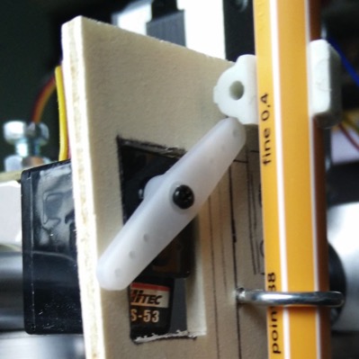
Servo to raise/lower the pen
Close view of the servo arm in the upper position raising the pen.

The Pen gets a little clamp attached (the one shown is a size 8 one to attach cables to walls). The servo arm can then raise the pen. When the arm goes down, gravity will also lower the pen.

Driving the servo

Driving the servo is relatively straightforward. One has to only provide the position and the servo does all the work.

#include <Servo.h>

// Servo pin
#define servoData PIN_A1

// Positions
#define PEN_UP 10
#define PEN_DOWN 50

Servo penServo;

void setup() {
  // Attach to servo and raise pen
  penServo.attach(servoData);
  penServo.write(PEN_UP);
}

I am using the servo headers on the Motor 4 place of the FabScan shield, so the pin to use is Analog pin number one.

Lowering the pen is then as easy as

  penServo.write(PEN_DOWN);

Next

One of the next steps is to add some end-detectors (but I may skip them and use the StallGuard mode of the TMC2130). Those detectors can then also be used to implement a home command

And then perhaps in the future I add a real z-Axis than can hold an engraver to do wood milling or PCB drilling or engraving of acrylic or .... :-) (A laser comes to mind as well).

More ...

That's it for now. The software is available at https://github.com/pilhuhn/xy-plotter and comes without any warranty.

My original announcement tweet

Thursday, March 17, 2016

Reacting on IoT data with Hawkular

In the first post I have been talking about how send IoT sensor data to the metrics subsystem of Hawkular and then how to register the metric in Hawkular so that it can be graphed in the console.

In this article I will talk about how the Hawkular alerts component (that is already available in Hawkular-full) can be used to react on incoming data and make an LED on an Arduino blink.

DSC 0160
Arduino Uno with Ethernet shield and yellow LED

For the Arduino I have added a cheap Enc28j60 based Ethernet shield. There is a standard library available, that allows to easily set up a web server, which we are using (in fact the code is mostly from that example).

The new (full) setup is like this:

Hawk alert
Setup with Arduino as actor

Alerting

Hawkular already has an alerting component built in, that allows to compare incoming values with thresholds and then invoke plugins to forward the fired alert via email, to irc channels and many more way of communication. The plugin we are going to use here is the webhook one. As in the standard Hawkular distribution only the email plugin is present we will need to install the webhook plugin first:

Check out Hawkular-alerts

git clone https://github.com/hawkular/hawkular-alerts.git
cd hawkular-alerts

Build hawkular alerts :

mvn -Pdev -DskipTests install

Now you can copy the plugin to the Hawkular-server

cd hawkular-alerts-actions-plugins
cd hawkular-alerts-actions-webhook
cp hawkular-alerts-actions-webhook.war \
   $HAWKULAR/modules/system/layers/hawkular/org/hawkular/nest/main/deployments/

As Hawkular does not pick this up automatically you need to restart the Hawkular server after copying the webhook.war over.

Set up alerting

I have modified the ruby script to pull in a configuration file (in YAML format):

---
16617927:40.176.91.120.5.0.0.125:
  :name: Living room
  :alert:
    :comparator: :gt
    :value: 25
The first line is the id of the metric to which the following lines apply to. Second line is the display name for the UI. The next section then sets up alerting.

Let's have a look how this looks in code (you can see the full code on GitHub)

Register the webhook to be used below:

@webhook_props = { url: 'http://172.31.7.177/',   # target server
                   method: 'POST' }               # http verb
@alerts_client.create_action 'webhook', "send-via-webhook-#{metric_id}", @webhook_props

Set up a trigger and a condition, trigger first

  t = Hawkular::Alerts::Trigger.new({})
  t.enabled = true
  t.id = "trigger_#{metric_id}"
  t.tags = { :resourceId => "#{feed}/#{res_id}" }
The tags tell the UI on which resource the Trigger applies and thus enables showing the alert in the Hawkular UI

Next the condition:

  c = Hawkular::Alerts::Trigger::Condition.new({})
  c.trigger_mode = :FIRING
  c.type = :THRESHOLD
  c.data_id = metric_id
  c.operator = alert[:comparator].to_s.upcase
  c.threshold = alert[:value]

And then finally as we do not only want the alert to show in the UI, but also be forwarded to our Arduino with the webhook, we need to attach the webhook to the Trigger. Plugin id is webhook and the action_id is what we have set up above.

  # Reference an action definition
  a = Hawkular::Alerts::Trigger::Action.new({})
  a.action_plugin = 'webhook'
  a.action_id = "send-via-webhook-#{metric_id}"
  t.actions.push a
And then we can create the trigger, which will be active immediately.

  @alerts_client.create_trigger t, [c], nil

Fire away

Now when a value above the threshold comes in, the webhook will be triggered, it will open a http connection to the Arduino and the LED will blink.

In addition the alert will also be shown in the Alert Center in the Hawkular UI:

Bildschirmfoto 2016 03 17 um 16 32 37
List of high temperature alerts in the alert center.

More

Note that the above trigger definition is pretty simple and only has one comparator. Also the trigger fires each time a value above the threshold comes in. In a more real world scenario one would add some dampening that the trigger only fires when the measurement is a few times over the threshold for some interval. Or if you start your air-conditioning, you would set the trigger to auto-disable and then have a comparator to switch it back on after the temperature has fallen below a certain level.

There is even a lot more you can do with Hawkular Alerts past the above, including standalone deployment for embedding it in your own application.

Some further reading:

Hawkular Alerts for Developers -- pretty comprehensive documentation of Hawkular Alerts.
Introduction to AutoResolve triggers
Using Hawkular Alerts as a standalone engine

Monday, February 22, 2016

Flashing new NodeMCU Lua firmware to Adafruit Huzzah ESP

Adafruit delivers the Huzzah ESP with NodeMCU 0.9.5, which is pretty old.

So I was thinking of a newer version. The process is pretty well described on nodemcu.readthedocs.org. Unfortunately it also says

The address for esp_init_data_default.bin depends on the size of your module's flash. ESP-01, -03, -07 etc. with 512 kByte flash require 0x7c000. Init data goes to 0x3fc000 on an ESP-12E with 4 MByte flash.

After digging through Adafruit docs (they do not explicitly mention the type of ESP) and also looking at the output of node.info() I figured out that the Huzzah ESP has an ESP12 with 4MB

I got my self a new image from the awesome on demand build service and then flashed it like this:

$ python esptool.py --port /dev/cu.usbserial-AI02CSDU \
   write_flash 0x00 ../nodemcu-master-15-modules-2016-02-18-08-33-47-integer.bin \
               0x3fc000 ../esp_iot_sdk_v1.4.0/bin/esp_init_data_default.bin
Connecting...
Erasing flash...
Took 2.12s to erase flash block
Wrote 423936 bytes at 0x00000000 in 45.8 seconds (74.1 kbit/s)...
Erasing flash...
Took 0.10s to erase flash block
Wrote 1024 bytes at 0x003fc000 in 0.1 seconds (85.4 kbit/s)...

Future updates of the firmware to newer versions no longer need to flash the esp_init_data_default.bin file.

Tuesday, January 05, 2016

Arduino powered X-Mas tree

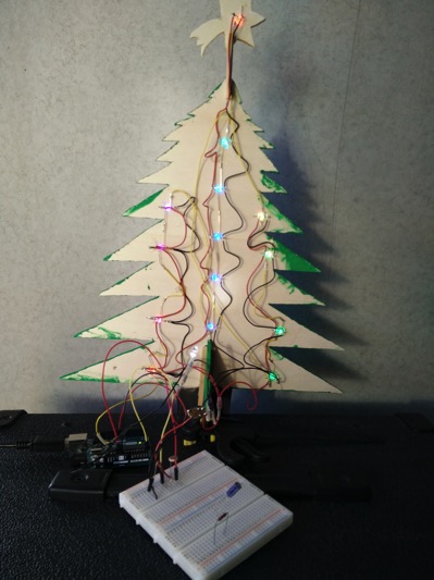
In 2014 we got two cats and decided not to have a classic christmas tree. I also started playing with Arduino and other gadgets, so this made me think to have an Arduino powered tree in 2015. In November my daughter and I started to build the tree.
The tree
The tree has 14 RGB LEDs (basically WS2812 ones) from Sparkfun (or EXP-Tech).
Pinout of the LEDs is as follows:
LED Pinout
LED-Pinout (click to enlarge)
.
With that, the tree wiring got relatively easy by bending the LED pins in the four different directions and then connecting all 5 Volt pins with the red wire, GND with the black and chaining data in and out either by directly soldering the pins or via the yellow wire:
Backside of the tree
Detail view:
Wiring detail
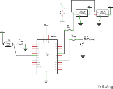
The overall schematic then looks like this (I am using an Arduino at the moment, but will use a TrinketPro in the future):
Weihnachtsbaum Schaltplan
Schematic (click to enlarge)
I've added a photo resistor and a white diode to provide some lighting of the tree front, as at night, the RGB LEDs are so light, that the tree itself can't be seen. The resistor value also serves to dim the RGB LEDs at night.
The software driving the LEDs is basically the Strandtest one that Adafruit delivers as example for their Neopixel Library. I've modified the code a bit to also show other patterns.
In the future we will add a stand for the tree that will also house the electronics and will also host some additional surprise that I will talk about in a future post :)

[ UPDATE 2016-12-11 ]

I've added a stand and the dedicated TrinketPRO:


Tuesday, October 06, 2015

Driving a Servo on Arduino from a remote Arduino over secured radio

In Stuttgart, there is now a Hackergarden Meetup group that tinkers with whatever the people showing up want to tinker with.

In the 1st edition I was doing some hacking on Arduino where two Arduinos were transmitting data over an encrypted radio via a RFM69 radio chip. This setup is described on the Codecentric blog.

Now in the 2nd edition we wanted to build on this and control a servo motor on one Arduino remote from the other one. This video shows the end result:

On the left you see a potentiometer, that is read out and the value is then shown on the Neopixel ring. The value is also transmitted via RFM69 chip to the other Arduino that has the receiver and which then drives the servo.

The setup on the server side looks like this:

Poti data sender Steckplatine

On the receiver side we used a "normal" setup like the one described on the before mentioned report. We had an issue for a while, as the servo was on a port that was also used by the RFM69 code, but once we fixed that, it worked.

The client side code is in my GitHub fork of the Hackergarden repository - I hope it will be merged soon :)