
But this would have been a little exaggerated at first and perhaps RHQ is - if you don't have other stuff to monitor and manage - like to break a butterfly on a wheel. But anyway a system like RHQ is (or will be) well suited to be the central brain of a home automation system. Of course, if I say RHQ, this applies to JBossON 2 as well.
A bit of background
I was for the start just looking for a cheap USB thermometer, but was unable to find such a beast. What
I found was a relatively cheap temperature sensor at German electronics dealer Conrad electronics, but the usage wasn't simple to decode first :) So I searched further.
Inspired by an article in German Linux Magazin, I started to look at the 1-wire protocol (which the above sensor uses) by Maxim. This 1-wire bus can operate many devices daisy chained together. Each device has its unique id, so it can be directly addressed by it (and which also suits nicely the unique resource key constraint in RHQ). There is actually a whole bunch of devices for the 1-wire bus like hubs, power injectors, actors and sensors available -- even a LCD.
The first thing that is needed is an USB-Adapter DS9490R (I got it from http://www.1-wire.de/ here in Germany, there should be other vendors like e.g. Hobby Boards).
Next, we need a thermometer chip like the DS18S20. In addition some wire, a RJ11 connector, a soldering iron and some solder. For the wire you can just take an old telephone cord that has the RJ connector still attached.
Doing some hardware work
I hope you know on which end you have to hold a soldering iron :-)
(If not, get a DS9490B with a iButton version of the DS1820 (DS1920) and skip this section :-)
Ok, if not yet done, hook up the wire to the RJ11 connector. Actually we only need the middle two pins, that are marked in the next example:
- RED (pin 3= data)
- Green (pin 4 = GND)
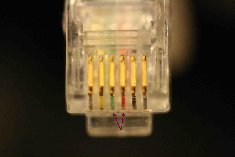
If this is done, heat up the soldering iron. On the DS18S20, you also only need two of the three pins, the rightmost can be used for external power, but is not needed in our case.
You have now to attach the wiring to the chip: put the ground (green in my example) on the left pin and the data line on the middle one - this could look like on the next image:
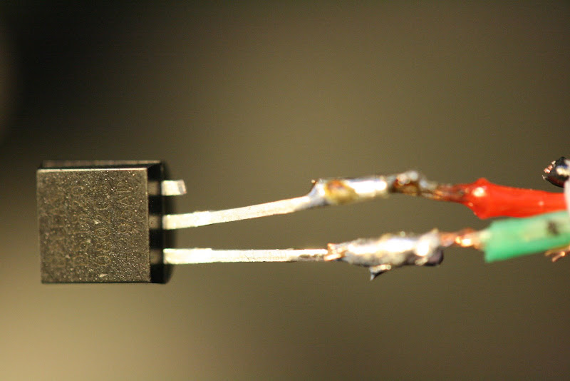
At the end, put some isolation (duct tape) between the pins and wires and you are ready to go.
Installing the needed software
The installation of the needed software is a little hairy.
Basically it follows the example from comment #5 on this blog posting. It is written for Mac OS X, but will apply with minor changes to other systems as well.
- Download libusb and install it into
/usr/local - Download the PDK from http://globalreset.org/files/distribution/PDKAdapterUSB.tar.gz. Compile this by running
make. If you are not on a Mac you probably need to change a few compiler settings. If this succeeded, you can run a test program viamake test. This should output some stuff -- and especially that the adapter has been found. If you have attached the sensor to the adapter, it should print two lines that start on 'adress:' (e.g.:
find first: true
address: D70008017DFCC410
address: 5D0000002B3C2081
Install the createdlibonewireUSB.jnilibto/Library/Java/Extensions/(if you are on a Mac, ymmv else). - Download the 1-wire SDK from Maxim. This package contains a jar archive
OneWireAPIsrc.jar-- extract this - Add the class
PDKAdapterUSB.classfrom the PDK into the right folder of the OneWire src that you just unpacked - Compile the classes from the OneWire sources and build up a jar archive (OneWireApi.jar).
If you want to use the example code from the OneWireApi, you have to modify OneWireAccessProvider.java to be able to load the PDKAdapterUSB. I also had to commend out a few java files for the serial adapter access, as they gave me compile errors). - Install the OWlib in your local maven repo like this (replace /Users/hrupp with the path to your maven repo):
mvn deploy:deploy-file -Dfile=OneWireApi.jar -DgroupId=com.dalsemi -DartifactId=OneWireApi -Dversion=1.10 -Dpackaging=jar -Durl="file:///Users/hrupp/.m2/repository/"
That's it for now, we now have all prerequisites. In the next posting I will describe how to write the RHQ part of this.
2 comments:
Need more infomation on the basic setup. Supposing I have a glasshouse located in a coulpe dozen meters from my house and I want to track the temperature in it (okay, may be in couple of more locations outdoors). As far as I see, I'll need this 1-Wire-USB interface from ibuttonlink (although can't understand, may be i need the similar model - LinkUSB without leter 'i'). Then I'll need wiring (okay, say, 20 meters), this temperature sensor and this T-probe to terminate the network (it will be located 5 meters from the first sensor). Do I have to buy any additional power supplies or USB power would be enough for my network? Where can I read about the basic setups?
I've been using this thing http://www.ibuttonlink.com/ds9490r.aspx to interface the 1-wire-bus to the computer. For sensors only, the USB power supply should be enough (perhaps put it on an active hub).
Maxim has a list of 1-wire products here: http://www.maxim-ic.com/auto_info.cfm those pages also contain informations about how to set things up along with data sheets etc.
Hope this helps you somewhat
Post a Comment